RESULTS OF MODELING, DESIGNING AND DEVELOPMENT OF BAND-PASS ELECTRIC FILTER WITH CROSS-LINKS IN WIDE RANGE OF ULTRA HIGH FREQUENCY BANDS
Abstract
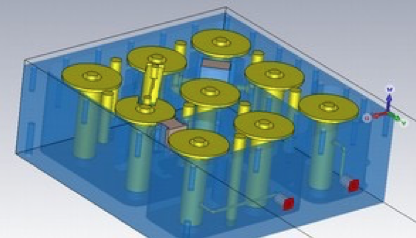
The provided analysis shows the need to ensure non-interference operation of radio electronic facilities (REFs) by eliminating the incompatible radio technologies in the adjacent frequency bands or by minimizing interference as far as possible. A presented example based on the cellular communication systems suggests that one of the factors influencing the size of a guard interval is the need to ‘filter-out’ nearby radio technologies operating in opposite directions of transmission. In such instances, filters shall be used to avoid interference. Filters will allow, in the first place, to create necessary attenuation in the reception band of BS of nearby radio technology to suppress out-of-band and spurious emissions, furnishing by BS own transmitter; and in the second place, to create attenuation in the transmission band of nearby radio technology in order to reduce signals coming from BS transmitters of nearby radio technology at the input of own BS receiver. Additional high slope AFR filters may be required for both the BS transmitters and BS receivers in some frequency ranges in Ukraine. There is one more precondition for usage of high slope AFR filters having the ability to suppress main emission of transmitters by values of 30-40 dB as follows: appropriate radio frequency control and regulatory authorities are required to apply the measuring equipment within dynamic range of 80 dB. The simplified 3D filter models on 9 coaxial resonators with high Q factor which are described in the article are prepared with the help of AWR Microwave office and CST Studio Suite software tools. The simulation of AFR and frequency response for such parameter as filter reflection coefficient is also described in the article. The results of design and research concerning band-pass electric filters that have been obtained on the basis of application of the low-frequency filter prototype method are presented in the article. Prototype models of band-pass electric filters with cross-links in wide range of UHF bands (820–843 MHz and 890–915 MHz, 1920–1980 MHz and 2510–2570 MHz) are designed and produced. As a result of measurements of AFR and frequency response for the filter reflection coefficient, the attenuation within the pass-band frequency range of these filters equals to 1.5–2.0 dB; the attenuation of input signals referring to out-of-band emissions equals to 30–75 dB; the filter reflection coefficient is within minus 13 dB.